
What's important to know is that the internal forces can be set in the project only in cases of modeling a structure with trimmed end, or ends. And also that this feature is available only for particular structures, namely the beam elements. For more information on the individual elements, go to Geometry types in Detail.
So, you shall know when you need to set the internal forces. Now, let's see how.
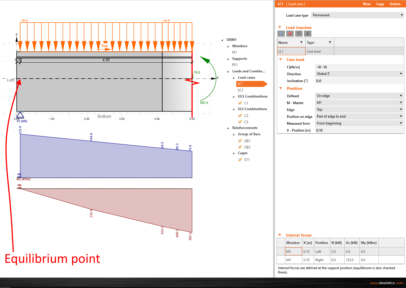
Single beam with an edge support
For this model, the equilibrium point is placed above the support at the edge of the beam. To reach the equilibrium, you have to define the loads as in the global model, and the values of the internal forces. In this particular case, the internal forces that need to be filled are, in fact, the reactions in the support taken from the global model, and set as a vertical shear force. To check the correctness of the results, see the diagram of the internal forces shown in the application's main graphic window. The software automatically calculates the values of the internal forces to the trimmed end of the beam, so in the end, you ought to see the same results for this exact spot as in the global model.
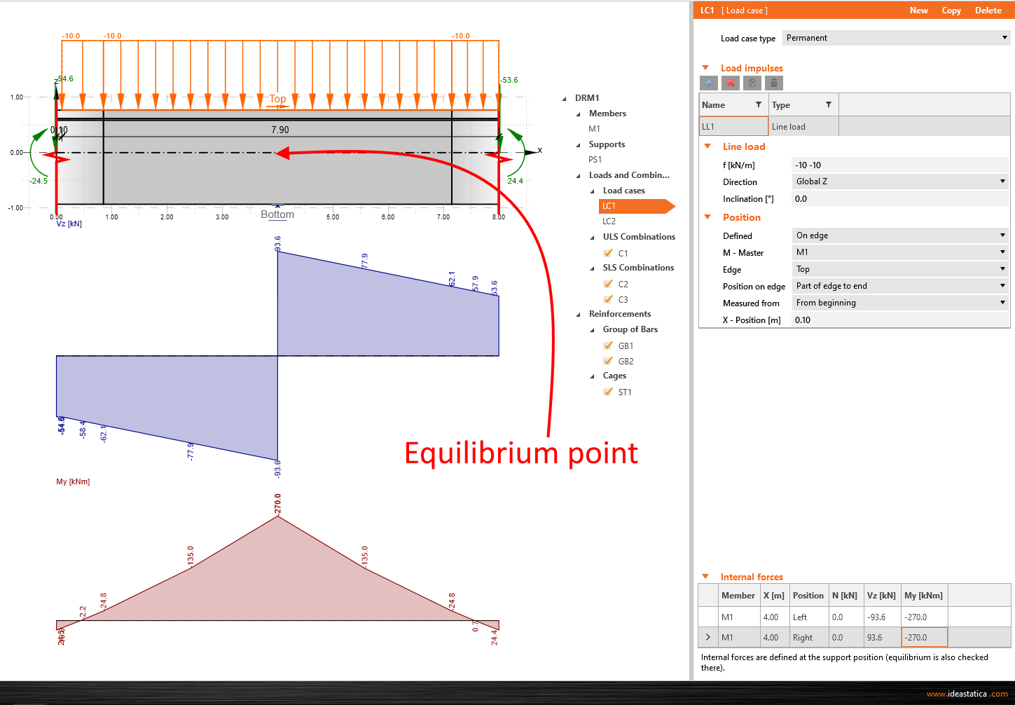
Single beam with a middle support
For this type, the equilibrium point is again placed above the support, and the approach is almost the same as in the case of the edge support example. The only difference is in the input of internal forces. You have to set them from both sides of the support. The correctness can be checked by looking at the internal forces diagram, and the reaction in the support - this value ought to be the same as the absolute summation of shear forces.
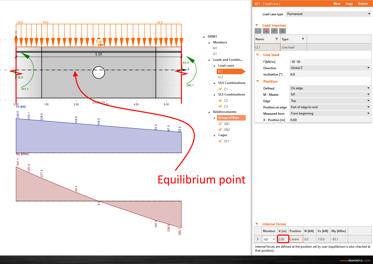
Single beam cutout
The last option of the single beam model. The same rules as in the previous examples are applied. Only in this case, you can manually adjust the position of the equilibrium point using the X coordinates related to the global coordinate system. So you fill in the values only for this specific point.
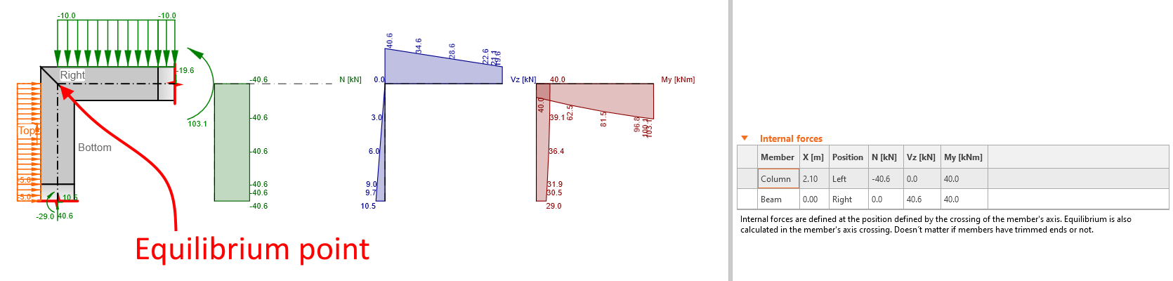
Knee joint
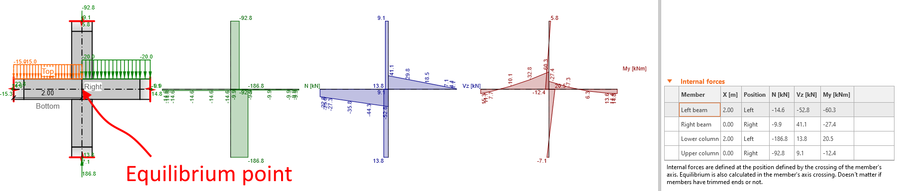
In the case of a frame joint, the equilibrium point, hence the position of the internal forces definition, is in the members' axis crossing - the node in the global model. Neither inclination nor joint type affects the definition of the equilibrium point.
Cross joint
The conditions of the internal forces input are the same as for the knee joint.
Practical Example
For a better understanding, watch the demonstration. In the following video, you will see how to insert the forces obtained from the global model. The example in the video is included earlier streamed webinar: Code-checking a column with bracket according to ACI using IDEA StatiCa.
Start your trial today and enjoy 14-days of full access and services free of charge.
Start free trial