Description
This study is focused on the verification of component-based finite element method (CBFEM) for the resistance of the symmetrical double splice slip-resistant connection to an analytical model (AM).
Analytical model
The slip resistance of a preloaded bolt is designed according to chapter 3.9.1 in EN 1993-1-8:2005. The preloading force is taken at 70 % of the ultimate strength of a bolt according to equation (3.7).
Verification of resistance
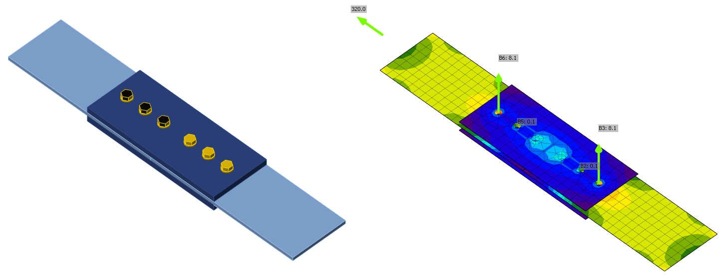
Design resistances calculated by CBFEM are compared with the results of analytical model (AM); see (Wald et al. 2018). The results are summarized in Tab. 5.6.1. The parameter is bolt diameter; see Fig. 5.6.1.
Tab. 5.6.1 Comparison of bolt resistance predicted by FE model to analytical one for bolt diameter; joint: splice 200/12 mm, bolts 2 × M× 8.8, plates 2 × 200/20 mm, steel S235
| Parameter | Analytical Model (AM) | CBFEM | AM/ CBFEM | |||
| Diam. | Distances | Resist. [kN] | Critical component | Resist. [kN] | Critical component | |
| M16 | p = 55 e1 = 40 | 211 | Slip | 205 | Slip | 1,03 |
| M20 | p = 70 e1= 50 | 329 | Slip | 320 | Slip | 1,03 |
| M24 | p = 80 e1 = 60 | 474 | Slip | 457 | Slip | 1,04 |
| M27 | p = 90 e1 = 70 | 617 | Slip | 594 | Slip | 1,04 |
| M30 | p = 100 e1 = 75 | 754 | Slip | 727 | Slip | 1,04 |
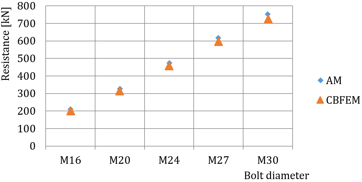
Fig. 5.6.1 Sensitivity study for the bolt diameter
The results of sensitivity studies are summarized in the graph in Fig. 5.6.2. The results show that the differences between the two calculation methods are below 5 %. Analytical model gives generally higher resistance.
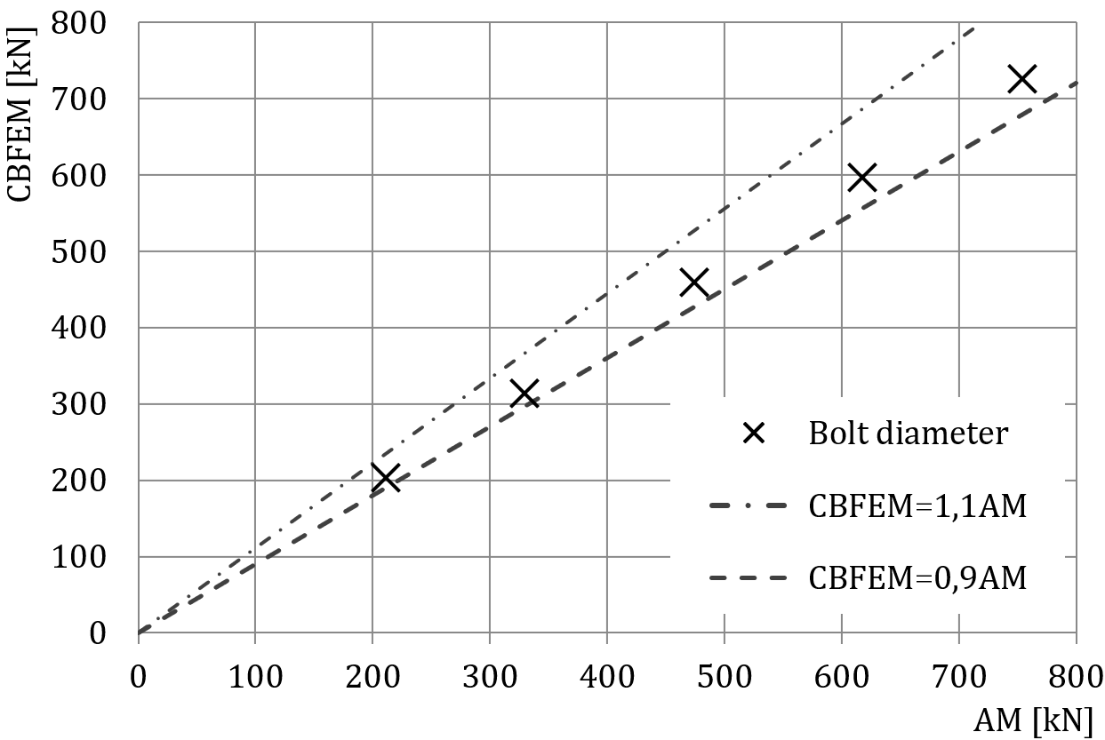
Fig. 5.6.2 Verification of CBFEM to AM for the slip-resistant double splice connection
Benchmark example
Inputs
Connected member
- Steel S235
- Splice 200×12 mm
Connectors
Bolts
- 3 × M20 8.8
- Distances e1 = 50 mm, p = 70 mm
Two splices
- Steel S235
- Plate 480×200×20 mm
Code setup
- Friction coefficient in slip-resistance 0.5
Outputs
- Design resistance FRd = 320 kN
- Design failure mode is slip of the bolts
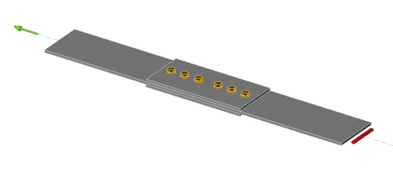
Fig. 5.6.3 Benchmark example of the bolted splices in shear