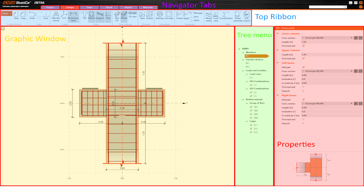
The application is divided into several sections. For better understanding, let's name and explain them.
- Tabs Navigator
- Top Ribbon
- Properties
- Graphic Window
- Tree menu
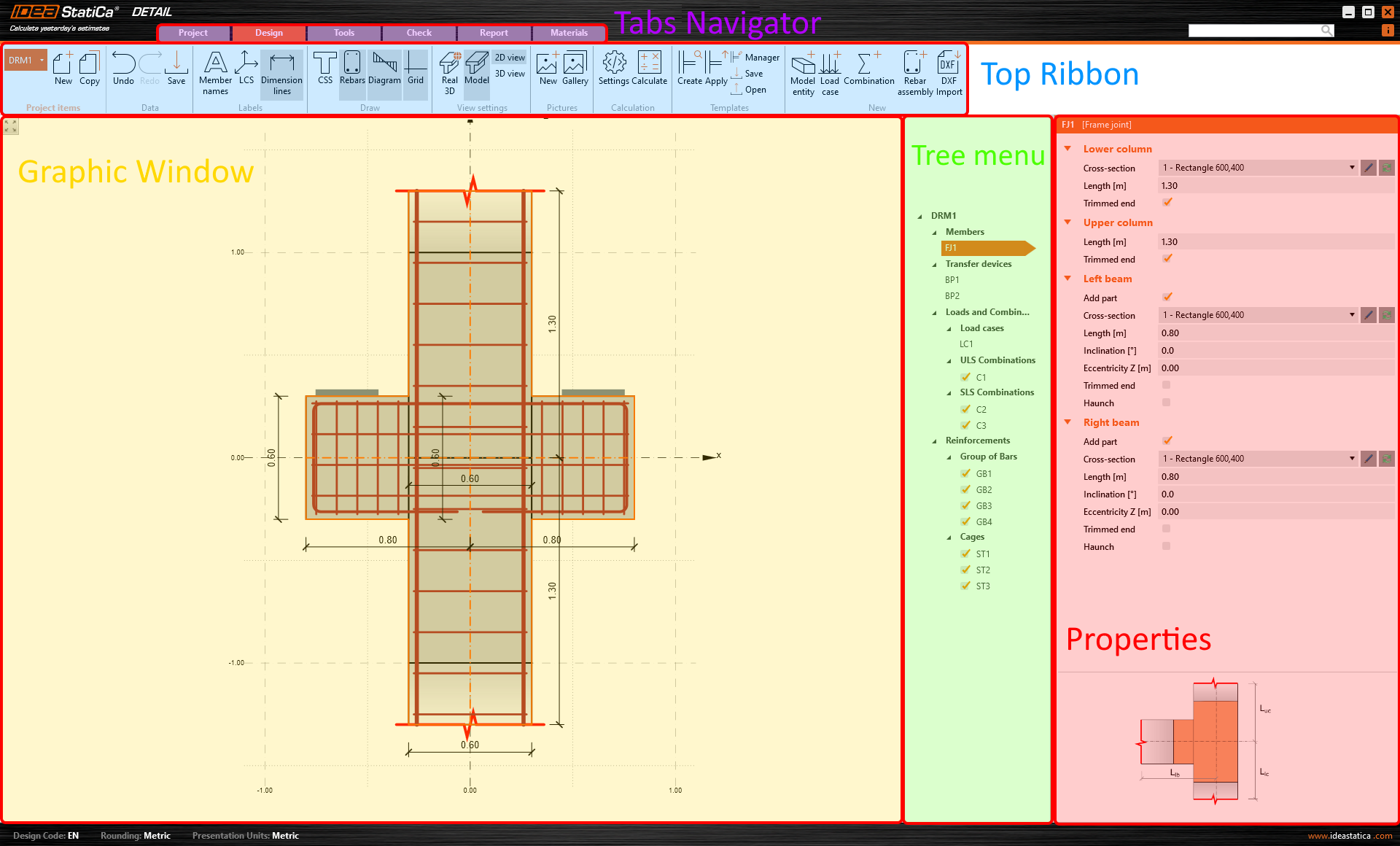
Tabs Navigator
The Tabs Navigator is a graphical control element in the form of toolbars divided into several tabs. In other words, various toolbar sets are provided for specific steps of modeling.
Top Ribbon
At the top ribbon, you'll see distinct sets of toolbars, each designed for specific stages in the modeling process. Under these toolbars, you will find the steps to follow when creating and editing the model.
Properties
In this section, you enter all the data. The layout of the Properties section varies according to the specific step from the Top Ribbon.
Properties always display. The rest of the tabs vary according to the specific step as different options are available when for example, changing the geometry or checking the results.
Graphic Window
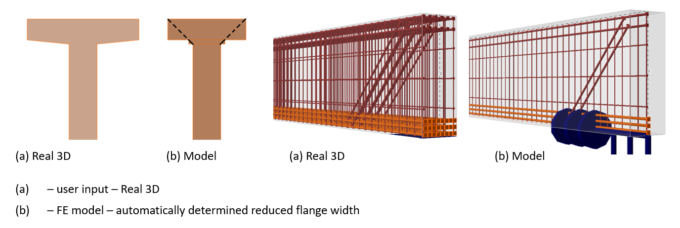
This is the main graphical window in the application. You will see all the changes and views you have set up in the project here. You can control the displayed model in the view settings in the Top ribbon. You can switch between 2D or 3D views and Real 3D or Model views.
If the Real 3D is activated, the user input displays (without modification). If the Model view is activated, the automatically determined view with reduced flange width displays. Notice also the difference between the Real 3D and Model views of the reinforcement.
For more information, read the knowledge base article:
Tree menu
A tree menu refers to a hierarchical navigation represented as a tree-like list. This visual representation helps easily comprehend the relationships and hierarchy of content within the software interface. It is adjusted according to the specific stage of the modeling process.
Search bar
When you need help, write keywords describing the problem into the Search bar. You will be immediately redirected to the support center.
Start your trial today and enjoy 14-days of full access and services free of charge.
Start free trial