Idea Statica
Steel
Steel overview
Connection design
Member design
Parametric design
Steel case studies
Concrete
Concrete overview
Walls and D-regions
Anchoring design
Concrete case studies
BIM & Workflows
BIM Overview
Supported integrations
Checkbot
Viewer
APIs
Support & Learning
Support Center
E-learning & certification
Blog
Downloads & Licensing
Pricing
Plans
Free community tool
Enterprise customers
Students & educators
How much will you save?
Company
About us
Contact
Research & development
Authorized resellers
Meet our customers
14-Day Trial
Support CenterKnowledge BaseShear force position input and visualization
How to define correct load position (Forces in)
Equilibrium and supporting member
Key insights into constraints, member length and GMNA vs MNA analysis
When to use a stiffening member?
How to model a single bolt connection (Model type)
Shear force position input and visualization
Default member length in Connection
The right LCS (local coordinate system) orientation
How to use a rod member
Relative positions of members
Steel joint analysis model
Different ways to define load effects
Equilibrium and supporting member
Principles of Loading in a Connection: Equilibrium, bearing member etc.
Key insights into constraints, member length and GMNA vs MNA analysis
Calculate load extremes
Shear force position input and visualization
When a shear connection transmits a bending moment
Loads in equilibrium by default
How to import load effects from Excel sheet
Percentage loading
Node equilibrium in the 3D FEM model
Internal forces in the steel connections
The right LCS (local coordinate system) orientation
Shear force position input and visualization
SteelConnection designKnowledge baseConnectionLoad effects

Shear force position input and visualization

This article is also available in
ENCSDEITNL

Setting the proper position of the shear force is essential for correct connection design. The modeling process becomes faster and more straightforward thanks to the updated way the software allows you to set the force position and immediately see the bending moment course due to unit shear force.

An option for setting the shear force position in a connection has been implemented to ensure smoother modeling. On top of that, you can see the bending moment diagram due to unit shear force immediately!

Let's have a look at the features one by one.

Shear force position at the member face

In many cases, the shear force position is assumed at the member face. You can face this situation when designing a connection with, e.g., a cleat, a short end plate, a flexible support, etc. We have developed a way of inputting the shear force position so you can become more efficient and get rid of tedious, repetitive work. 

You can set the position using the Connected member face functionality. The software will set it automatically according to the connected member's surface. That means no more manual adjusting using coordinates. And with the change of cross-sections, the position is still kept.

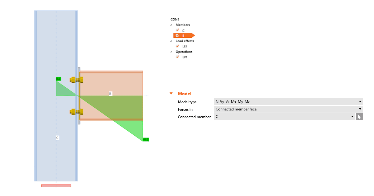
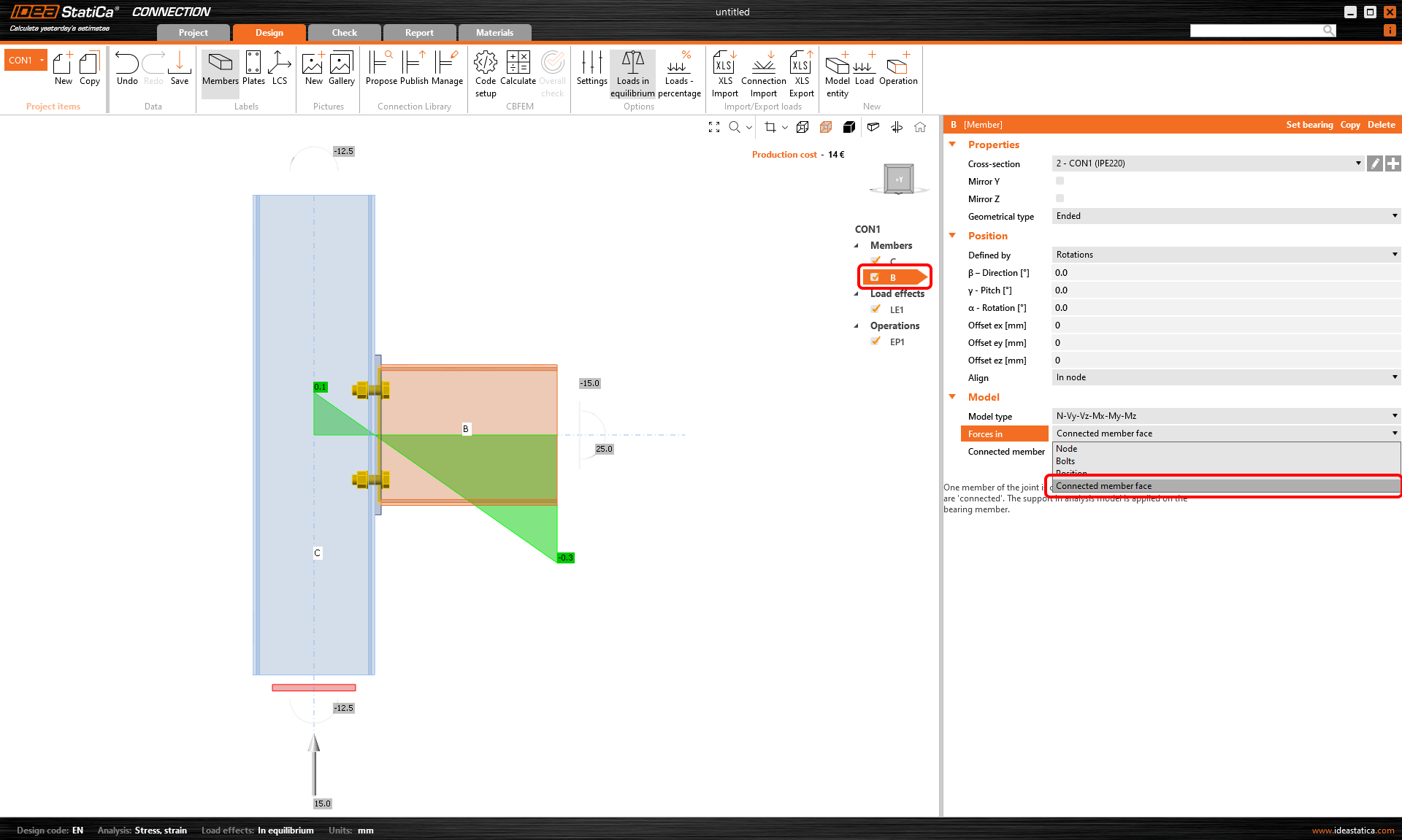
How does it work? Simply select the member for which you want to set the force position, and select the Connected member face option in the Forces in section under Model in the property tab. It is recommended to always select the connected member manually.

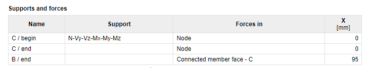
The method and position are also shown in the report.

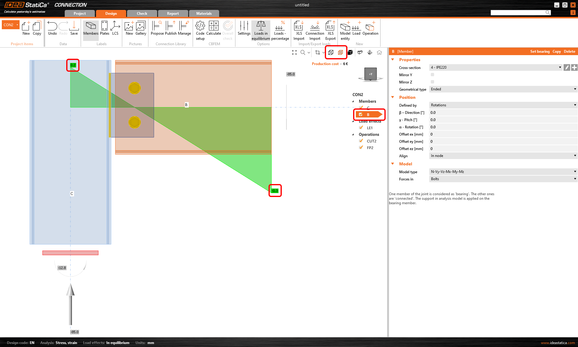
A better way of shear force position visualization

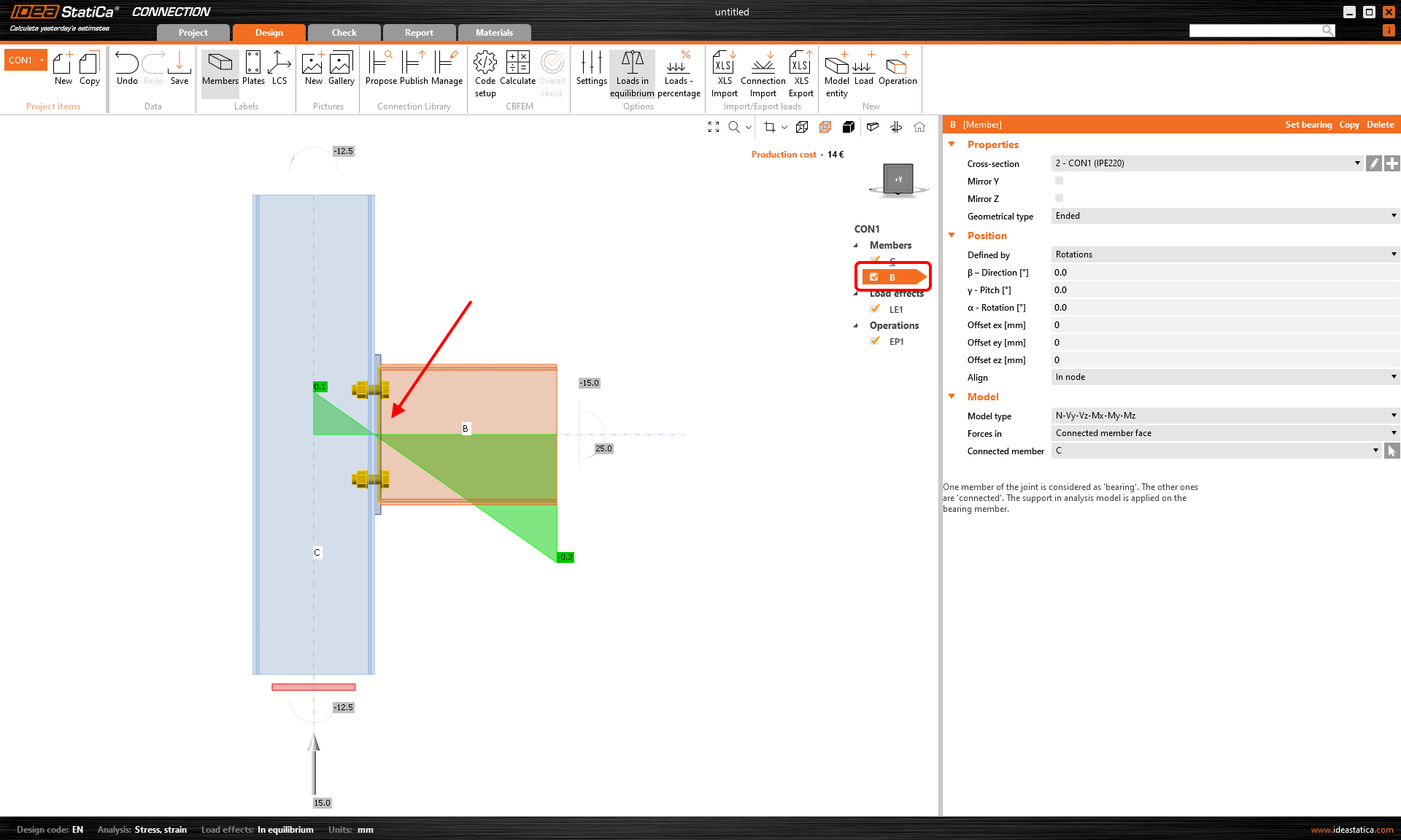
The Connection application now shows you the value of the bending moment from the unit shear force Vz=-1 for every modeled connection. The unit is according to the unit setting (e.g., Vz= -1 kN or -1 kip). The bending moment also respects the unit settings (e.g., kNm or kip-ft).

The diagram can be shown in Transparent or Wireframe visualization mode, i.e., select the member for which you want to see the diagram, and use one of these modes.

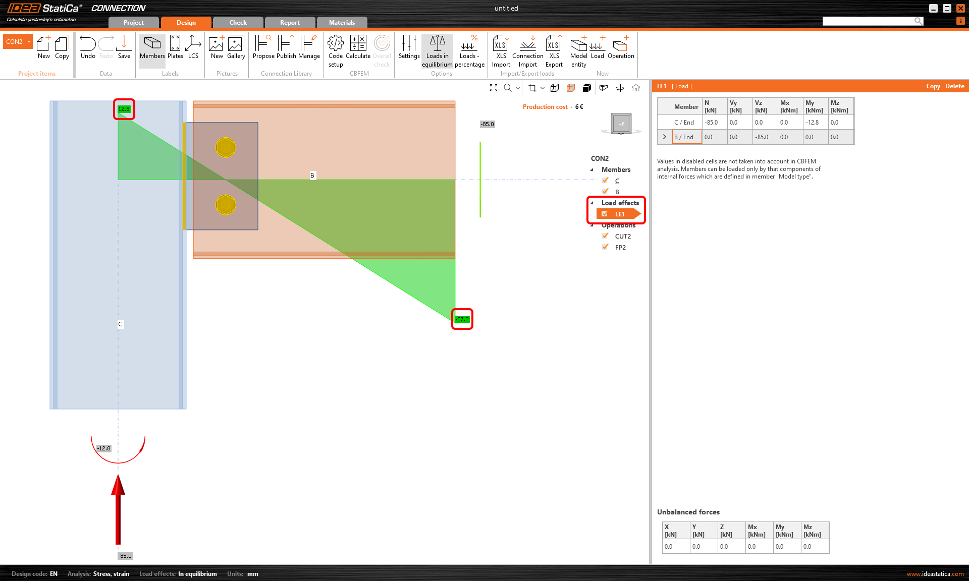
The real moment diagram using the load effects input is still shown in the Load effects section.

Available in IDEA StatiCa Steel and IDEA StatiCa Complete editions.

Download the latest version for free

Subscribe to our newsletter

Company

  • About us
  • Partnerships
  • Job openings
  • Patented technology for structural engineers

Resources

  • Customer projects
  • Case studies
  • IDEA StatiCa Connection Library
  • Concrete verifications

Legal

  • IDEA StatiCa END USER LICENSE AGREEMENT
  • Privacy policy
  • Terms of Services – IDEA StatiCa Viewer
  • Licensing

Help

  • Contact
  • Get price quote
  • IDEA StatiCa Specialists
  • Download the latest version
FacebookInstagramLinkedInYouTube

© IDEA StatiCa 2009-2026

Trusted and used worldwide by engineers, fabricators & consultants.