

Description
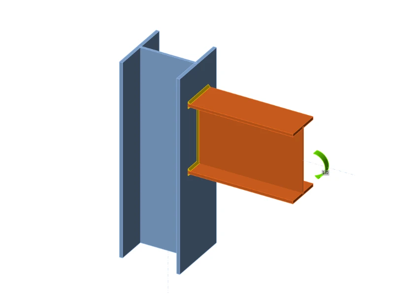
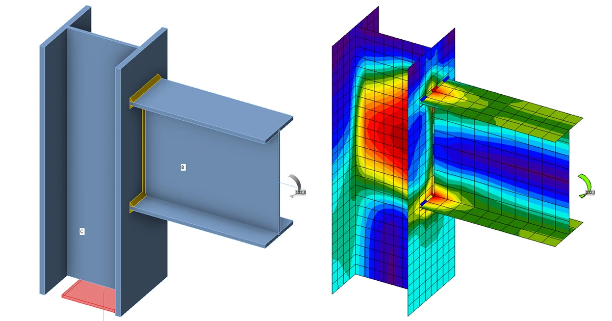
The prediction of rotational stiffness is described on a welded eaves moment joint. A welded joint of open section column HEB and beam IPE is studied, and the joint behavior is described on a moment-rotation diagram. The results of the analytical model by component method (CM) are compared with the numerical results obtained by the component-based finite element method (CBFEM). A benchmark case is available.
Analytical model
The rotational stiffness of a joint should be determined from a deformation of its basic components, which are represented by the stiffness coefficient ki. The rotational stiffness of the joint Sj is obtained from:
where:
- ki is the stiffness coefficient for the joint component i;
- z is the lever arm; see 6.2.7;
- μ is the stiffness ratio; see 6.3.1.
The joint components that are taken into account in this example are column web panel in shear k1, column web in compression k2, and column web in tension k3. The stiffness coefficients are defined in Table 6.11 in EN 1993-1-8:2005. The initial stiffness Sj,ini is obtained for a moment Mj,Ed ≤ 2/3 Mj,Rd.
where
— rotational stiffness of the joint
= 2.7 — EN 1993-1-8 table 6.8
An open section beam IPE 400 is welded to a column HEB 300 in the example. Beam flanges are connected to the column flange with welds with the throat thickness of 9 mm. The beam web is connected with welds with the throat thickness of 5 mm. Plastic stress distribution is considered in welds. The material of the beam and column is S235. The design resistance is limited by the components column panel in shear and column panel in transverse compression . The calculated stiffness coefficients of the basic components, initial stiffness, stiffness by design resistance, and rotation of the beam are summarised in Tab. 10.1.1.

Numerical model
Detailed information about the prediction of stiffness in CBFEM may be found in chapter 3.9. The same eaves moment joint is modeled, and the results are in Tab. 10.1.2. The design resistance is reached by 5% plastic strain in the component column web in tension. The CBFEM analyses allow calculating rotational stiffness at any stage of loading.
Experimental overview
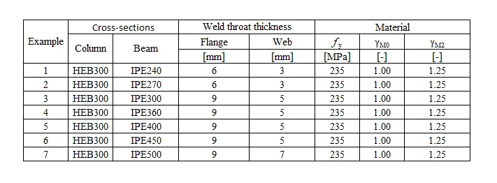
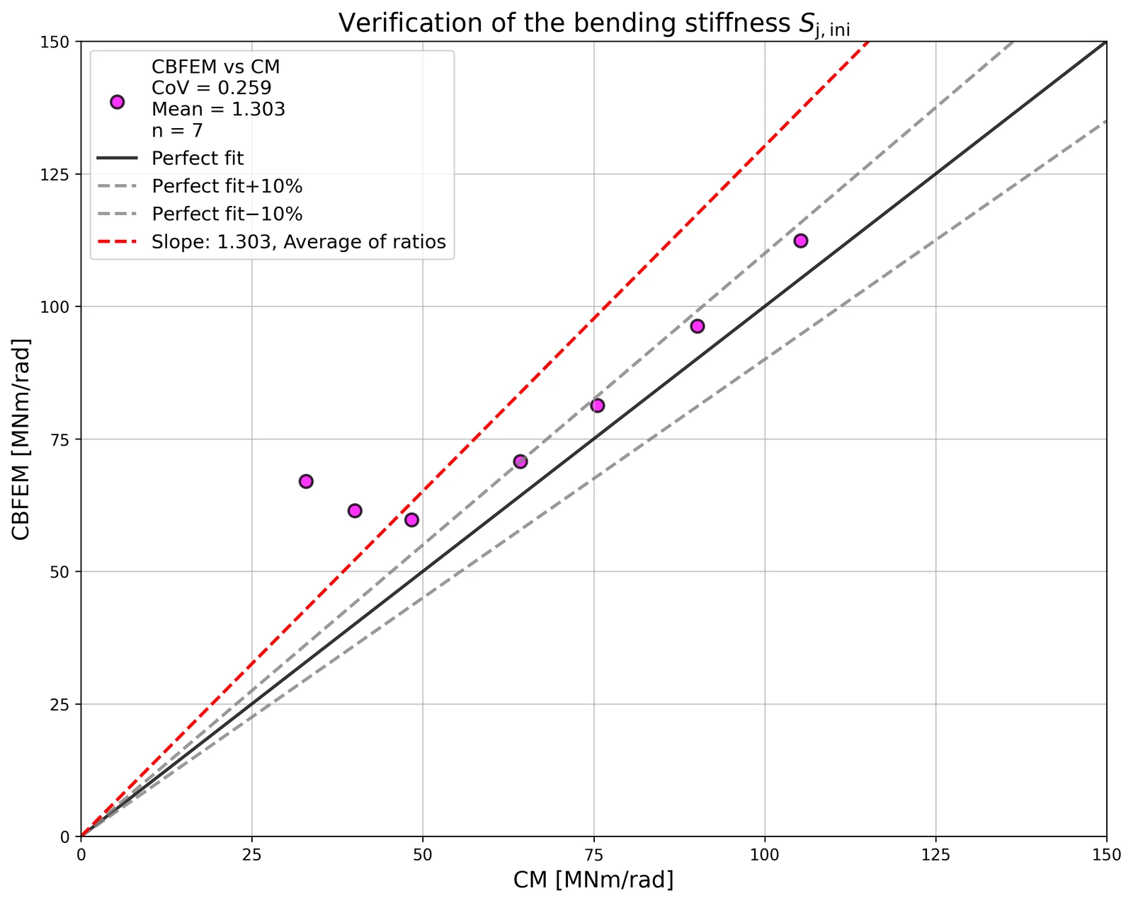
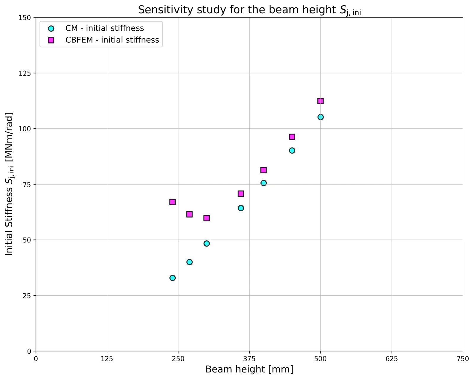
For the purpose of the comparison, a cross-section was set to HEB300 and the beam cross-section was variable. All materials utilised were S235.
Verification of stiffness
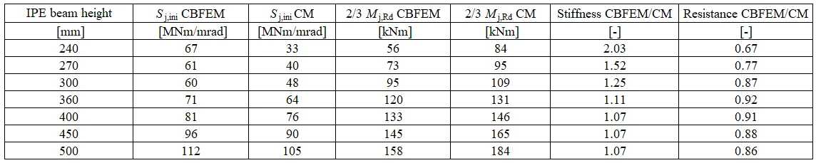
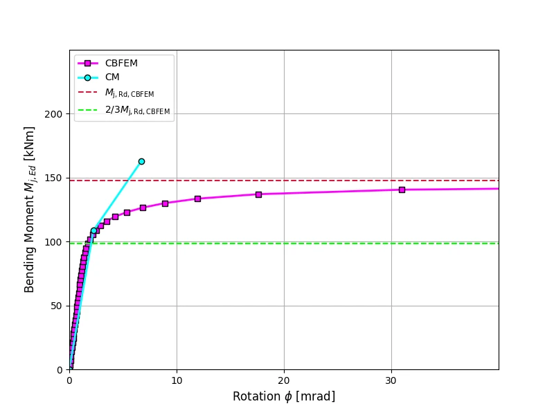
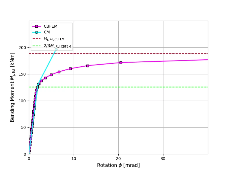
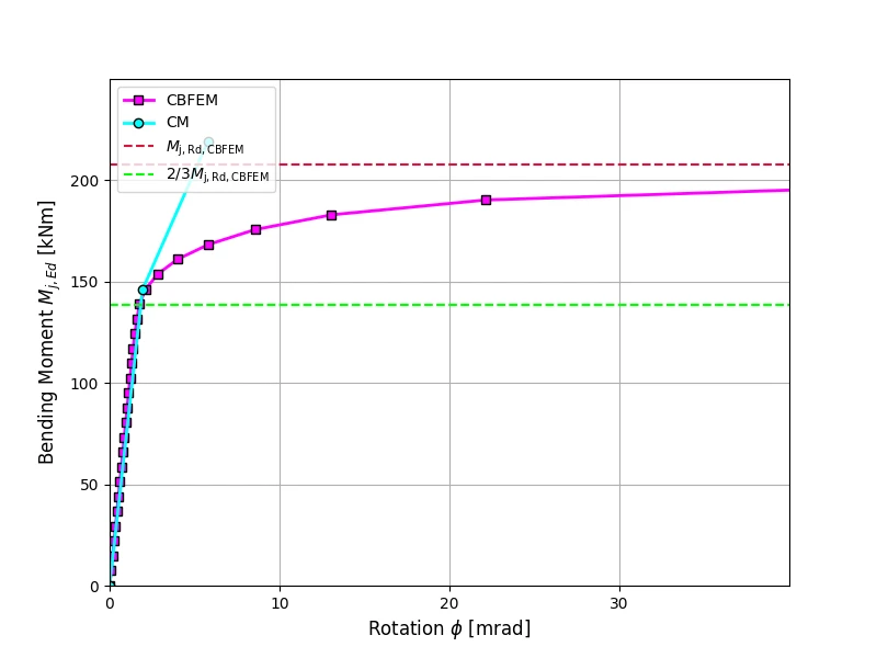
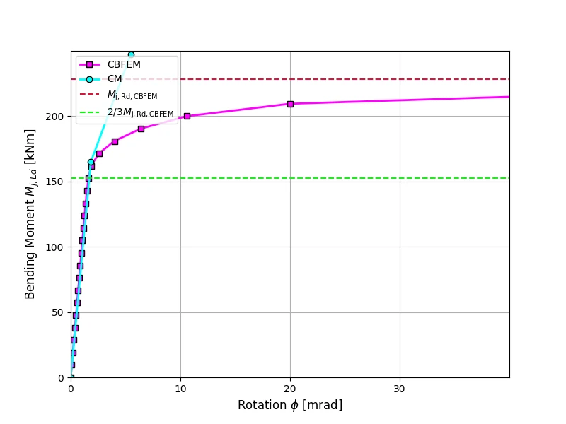
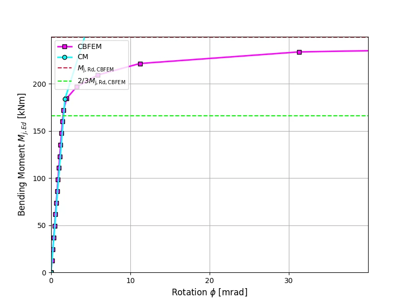
The rotational stiffness calculated by CBFEM is compared with CM. The comparison shows good agreement in initial stiffness and correspondence of joint behavior. The calculated stiffness from CBFEM and CM are summarised in Tab. 10.1.3.
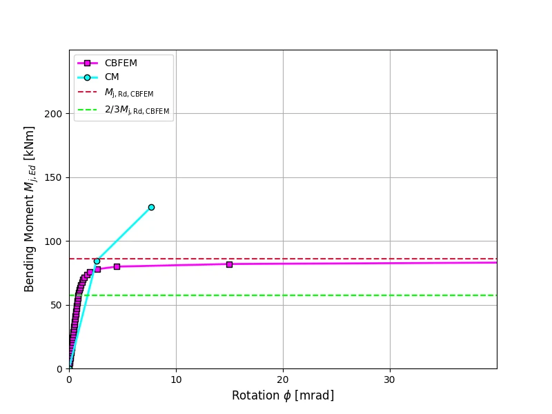
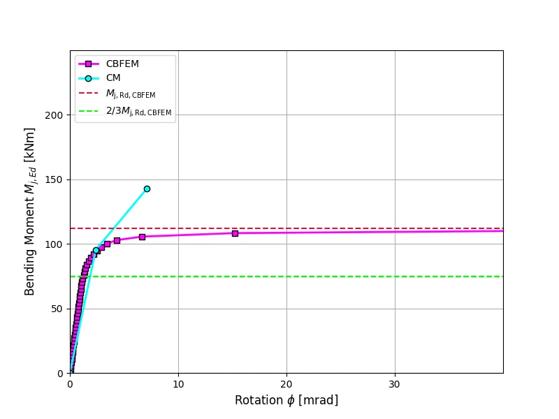
A comparison of the global behavior of a welded eaves moment joint described by a moment-rotation diagram is prepared. The joint is analyzed, and the stiffness of the connected beam is calculated. The main characteristic is the initial stiffness calculated at 2/3Mj,Rd, where Mj,Rd is the design moment resistance of the joint. The moment-rotation diagram is shown in Fig. 10.1.1.
Benchmark case
Inputs
Beam and column
- Steel S235
- Column HEB 300
- Beam IPE 400
- Flange weld throat thickness af = 9 mm
- Web weld throat thickness aw = 5 mm
- Column offset s = 150 mm
- Double fillet weld
Outputs
- Design resistance
- Load
- Secant rotational stiffness