Idea Statica
Steel
Steel overview
Connection design
Member design
Parametric design
Steel case studies
Concrete
Concrete overview
Walls and D-regions
Anchoring design
Concrete case studies
BIM & Workflows
BIM Overview
Supported integrations
Checkbot
Viewer
APIs
Support & Learning
Support Center
E-learning & certification
Blog
Downloads & Licensing
Pricing
Plans
Free community tool
Enterprise customers
Students & educators
How much will you save?
Company
About us
Contact
Research & development
Authorized resellers
Meet our customers
14-Day Trial
Support CenterKnowledge BaseCapacity design according to Canadian standards
Advanced analysis types for your steel structures
Seismic analysis in IDEA StatiCa Connection
Qualification checks of seismic prequalified connections for AISC
Prequalified Steel Connections (AISC) - Summary, Conclusion, and Recommendations
Steel connection capacity design
Capacity design (AISC)
Capacity design according to Canadian standards
Capacity design is a part of the seismic check and ensures that the joint has sufficient deformation capacity. IDEA StatiCa - engineering software for the structural design of steel connections and beams.
Connection designSteelKnowledge baseConnectionCBFEM

Capacity design according to Canadian standards

This article is also available in
ENNL

Capacity design is a part of seismic check and ensures that the joint has sufficient deformation capacity.

The objective of capacity design is to confirm a building undergoes controlled ductile behaviour in order to avoid collapse in a design-level earthquake. Plastic hinge is expected to appear in dissipative item and all non-dissipative items of the joint must be able to safely transfer forces due to the yielding in the dissipative item. The dissipative item is usually a beam in moment resisting frame but it may also be e.g. an end plate. The resistance factor is not used for dissipative items. Two factors are assigned to the dissipative item:

  • Ry = 1.1 – overstrength factor – S16-14, Cl. 27.1.7; editable in materials
  • Cpr = 1.1 – strain-hardening factor – S16-14, Cl. 27.2.2; it is recommended to apply for beam as a dissipative item in moment resisting frame

The material diagram is modified according to the following figure:

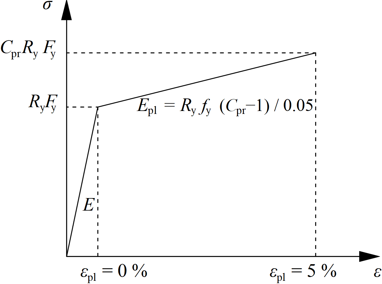
The increased strength of the dissipative item allows for the input of loads that cause the plastic hinge to appear in the dissipative item. In the case of moment resisting frame and beam as the dissipative item, the beam should be loaded by My = CprRyFyWpl,y and corresponding shear forceVz = –2 My,Ed / Lh, where:

  • Fy – yield strength
  • Wpl,y – plastic section modulus
  • Lh – distance between plastic hinges on the beam

In case of asymmetric joint, the beam should be loaded by both sagging and hogging bending moments and their corresponding shear forces.

The plates of dissipative items are excluded from check.

Subscribe to our newsletter

Company

  • About us
  • Partnerships
  • Job openings
  • Patented technology for structural engineers

Resources

  • Customer projects
  • Case studies
  • IDEA StatiCa Connection Library
  • Concrete verifications

Legal

  • IDEA StatiCa END USER LICENSE AGREEMENT
  • Privacy policy
  • Terms of Services – IDEA StatiCa Viewer
  • Licensing

Help

  • Contact
  • Get price quote
  • IDEA StatiCa Specialists
  • Download the latest version
FacebookInstagramLinkedInYouTube

© IDEA StatiCa 2009-2026

Trusted and used worldwide by engineers, fabricators & consultants.