
Fillet welds are checked according to AISC 360 - Chapter J2. The strength of CJP groove welds is assumed the same as the base metal and is not checked.
Fillet welds
The design strength, ϕRn, and the allowable strength, Rn/Ω, of welded joints are evaluated in the connection weld check.
ϕ = 0.75 (Load and Resistance Factor Design, LRFD, editable in Code setup)
Ω = 2.00 (Allowable Strength Design, ASD, editable in Code setup)
Available strength of welded joints is evaluated according to AISC 360-16 – J2.4
Rn = Fnw Awe
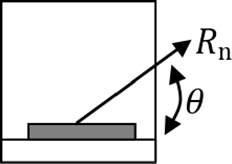
Fnw = 0.6 FEXX (1.0 + 0.5 sin1.5θ )
where:
- Fnw – nominal stress of weld material
- Awe – effective area of the weld
- Awe = Lc*Th
- FEXX – electrode classification number, i.e., minimum specified tensile strength
- θ – angle calculated between the longitudinal axis of the weld and resultant force direction acting in the most stressed finite element of the weld.
Note that directional strength increase is not used for welds where the edge of a rectangular hollow structural section is connected (AISC 360-16:2022 – J2.4.(2).
Base metal strength is evaluated if the option is selected in Code setup (Base metal capacity at the fusion face).
Rn = FnBM ABM – AISC 360-16 – J2.4 (J2-2)
where:
- FnBM = 0.6 Fu – nominal strength of the base metal – AISC 360-16 – J4.2 (J4-4)
- \( A_{BM}=A_{we}\sqrt{2} \) – cross-sectional area of the base metal
- Fu – specified minimum tensile strength
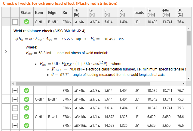
All values required for check are printed in tables.
where:
- Xu – used welding electrode
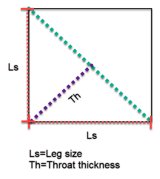
- Th – weld throat thickness (calculated from Ls)
- Ls – weld leg size (user input)
- \(L\) – total weld length
- \(L_c\) – length of critical weld element
- Loads – critical load effect for investigated weld
- \(F_n\) – force in critical weld element
- \(\phi\)Rn – weld resistance
- Ut – utilization of the critical weld element
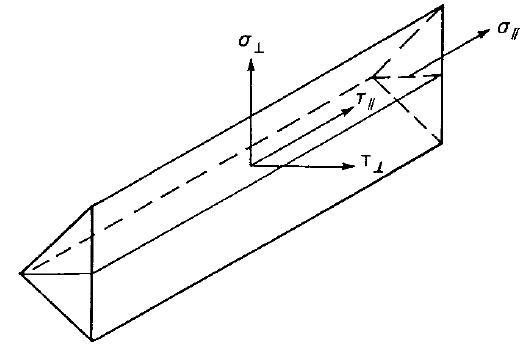
The force, \(F_n\), and weld angle, \(\theta\), are derived from stresses \( \sigma_{\perp}, ,\ \tau_{\perp}, \, \tau_{\parallel}\), length and effective area of weld finite element. These stresses are the basic output of finite element solver.
The weld diagrams show stress according to the following formulas:
If base metal is deactivated (matching electrode is used):
\[ \sigma = \frac{\sqrt{ \sigma_{\perp}^2 + \tau_{\perp}^2 + \tau_{\parallel}^2 }}{1+0.5 \sin^{1.5}{\theta}} \]
If base metal is activated (matching electrode is not used):
\[ \sigma = \max \left \{ \frac{\sqrt{ \sigma_{\perp}^2 + \tau_{\perp}^2 + \tau_{\parallel}^2 }}{1+0.5 \sin^{1.5}{\theta}}, \, \frac{\sqrt{ \sigma_{\perp}^2 + \tau_{\perp}^2 + \tau_{\parallel}^2 }}{\sqrt{2} F_u / F_{EXX}} \right \} \]
User Note: In IDEA StatiCa, when weld leg size is input as 0, the following value is used:
- For single-sided fillet weld, weld throat thickness equals the thinner connected plate.
- For double-sided fillet weld, weld throat thickness equals half of the thinner connected plate.
CJP groove welds
AISC Specification Table J2.5 identifies four loading conditions that might be associated with groove welds and shows that the strength of the joint is either controlled by the base metal or that the loads need not be considered in the design of the welds connecting the parts. Accordingly, when Complete Joint Penetration (CJP) groove welds are made with matching-strength filler metal, the strength of a connection is governed or controlled by the base metal and no checks on the weld strength are required.
PJP groove welds
The design strength, ϕRn, and the allowable strength, Rn/Ω, of PJP groove weld is determined according to AISC 360-22 – Table J2.5). The most conservative case – load type by shear – is assumed.
ϕ = 0.75 (Load and Resistance Factor Design, LRFD, editable in Code setup)
Ω = 2.00 (Allowable Strength Design, ASD, editable in Code setup)
Available strength of welded joints is evaluated according to AISC 360-16 – J2.4
Rn = Fnw Awe
where:
- Fnw = 0.6 FEXX – nominal stress of weld material
- Awe – effective area of the weld
- Awe = Lc E
- FEXX – electrode classification number, i.e., minimum specified tensile strength
- Lc – length of critical weld element
- E – effective throat of PJP weld
Base metal strength is evaluated if the option is selected in Code setup (Base metal capacity at the fusion face).
Rn = FnBM ABM – AISC 360-22 – J2.4 (J4)
where:
- FnBM = 0.6 Fu – nominal strength of the base metal – AISC 360-22 – J4.2 (J4-4)
- \( A_{BM}=A_{we} \) – cross-sectional area of the base metal assumed to be equal to the effective area of the weld
- Fu – specified minimum tensile strength of base metal